- Get link
- X
- Other Apps
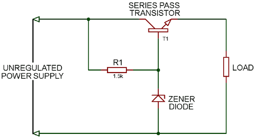
The below circuit shows the voltage regulator using transistor. The advantage of this circuit is that the changes in zener current are reduced by a factor ss.

Voltage Regulator From Discrete Components

Switch Mode Power Supply And Switching Regulators

Lm317 With Outboard Current Boost Circuit Homemade Circuit
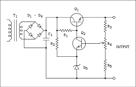
Although it is quite straightforward to use an operational amplifier which will provide higher levels of feedback and hence better regulation this two transistor circuit illustrates the principles well.

Transistor voltage regulator circuit. Discrete transistor voltage regulator. Disadvantage of transistor series voltage regulator. Discrete transistor voltage regulators can be classified into two.
They are explained below. All current flows were also revered. That completes this introduction to zener diode based voltage regulation.
In this article we will comprehensively discuss how to make or design customized voltage regulator circuits in fixed modes and also variable modes. A simple transistor regulator will provide a relatively constant output voltage u out for changes in the voltage of the power source u in and for changes in load r l provided that u in exceeds u out by a sufficient margin and that the power handling capacity of the transistor is not exceeded. This circuit provides the voltage regulation with wide load variations.
Transistor zener diode regulator circuits tricks and tips for the lm78xx series voltage regulators. Comparing with the zener voltage regulator it will provide better regulation. It is possible to use a simple two transistor circuit for a series pass regulator with voltage sensing and feedback.
A dc voltage regulator is a device which maintains the output voltage of an ordinary power supply constant irrespective of load variations or changes in input ac. The transistor series voltage regulator working is when the voltage at the transistors base voltage is held to the stable voltage across the diode. We use the simple zener diode voltage regulator as main ideas and two transistors to increase current to the load at 1a 2a.
In addition to that it will provide high current output with better stability. These two circuits are able to produce a regulated output dc voltage that is regulated or maintained at a predetermined value even if the input voltage varies or the load connected to the output terminal changes. Hence the effect of zener impedance is tremendously reduced and we get a more stabilised output.
The npn transistor was replaced with a pnp transistor and the polarity of the zener diode and 100uf capacitor were reversed. Advantage of transistor series voltage regulator. These circuits can be in the form of of permanently fixed or constant voltage or stabilized adjustable output voltage.
For instance if zener voltage is 8v the transistors base voltage will stay approximately 8v. This regulated power supply included a transformer t1 a bridge d1d4 and the 38v dc filtering voltage regulator circuits which consists of c1 c2 r1 r2 r3 q1 and q2.

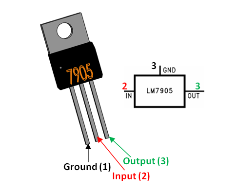
Lm7905 Negative Voltage Regulator Pinout Specs Circuit

The Proposed Voltage Regulator Transistor Level Circuit

Troubleshooting Chapter Five Faults In Power Supplies

Shunt Voltage Regulator Interfacebus

Transistor Zener Diode Voltage Regulator Circuit

Small Zener Diode Voltage Regulator Circuit With Pcb

Electronic Circuits Regulators Tutorialspoint

Transistor Bjt Zenner Diode Voltage Regulator Circuit

12 Volt 30 Amp Power Supply

Voltage Regulator Circuits Linear Voltage Regulator Zener

Increasing Regulator Current

What Does This Component Do In This Series Pass Regulator
transistor voltage regulator circuit
transistor voltage regulator circuit diagram
voltage regulator circuit using transistor
- Get link
- X
- Other Apps
Comments
Post a Comment